Frames and poses
Every number in a Cartesian target is a pose of the TCP relative to the working frame.
The planner solves for joint values q such that
where tcp_frame is the link the tool is mounted on and tcp_offset is the fixed transform from
that link to the tool point. Lengths are in metres, angles in radians, and quaternions are
scalar-last, [qx, qy, qz, qw].
flowchart LR
    ROOT(["root link<br/>(base_link on the IRB2400)"])
    ROOT -->|"joints q<br/>forward kinematics"| TF["tcp_frame<br/>e.g. tool0"]
    TF -->|"tcp_offset<br/>fixed"| TCP(("TCP"))
    ROOT -->|"scene graph"| WF["working_frame<br/>e.g. a workpiece link"]
    WF -.->|"CartesianTarget pose"| TCP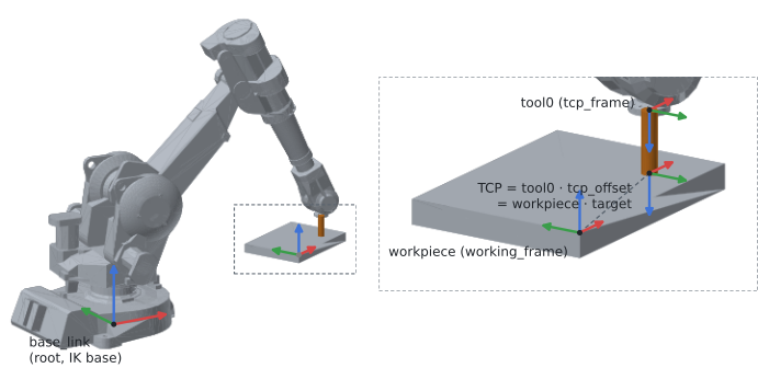
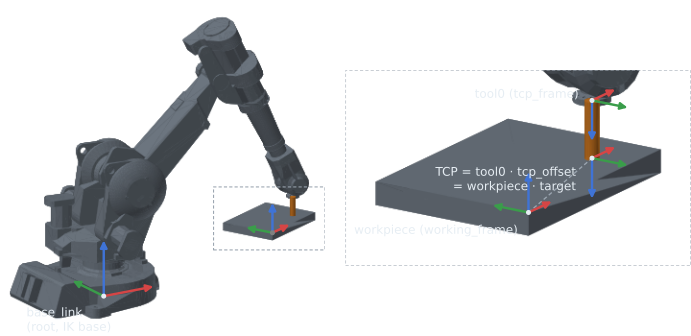
tool0 · tcp_offset, and a Cartesian target is a pose in the working_frame: the planner puts the first on the second. Here a workpiece frame sits on a plate corner, the target is 30 cm × 7 cm into it with the tool pointing down, and tcp_offset is 10 cm along tool0's z (the orange body is drawn only, the planner sees the offset). The arm is in the IK solution for target · tcp_offset⁻¹; every frame is drawn from forward kinematics, and the TCP lands on the target to 5e-12 m. On the IRB2400, the URDF's base frame coincides with base_link. Axes: x red, y green, z blue. Reproduce: pixi run docs-figures frames.The frames a program names
| Frame | Set by | Meaning | IRB2400 example |
|---|---|---|---|
| root | URDF | the scene graph's root link; every link pose is ultimately relative to it | base_link |
tcp_frame |
MotionProgram(tcp_frame=...) |
the link the tool is attached to | tool0 (the flange) |
tcp_offset |
MotionProgram(tcp_offset=...) |
transform from tcp_frame to the TCP: an Isometry3d, or the name of an SRDF group_tcps entry |
10 cm along tool0's z axis |
| TCP | tcp_frame · tcp_offset |
the point and orientation the target pose places | the tool tip |
working_frame |
MotionProgram(working_frame=...) |
the frame Cartesian targets are expressed in | base_link, or a workpiece link |
The planning API never picks a frame for you: tcp_frame and working_frame are required. A
working frame that is a link of the scene (a workpiece, a positioner's table) makes the targets
move with it: change the link's pose and the same program follows it.
Checking the relation
Forward kinematics gives tcp_frame in the group's base frame; composing with the offset gives
the TCP. Inverse kinematics solves for a link, so a target for the TCP is first moved back onto
the flange:
import numpy as np
from tesseract_robotics import get_tesseract_resource_path
from tesseract_robotics.common import GeneralResourceLocator
from tesseract_robotics.planning import Pose, Robot

locator = GeneralResourceLocator(paths=[get_tesseract_resource_path()])
robot = Robot.from_tesseract_support("abb_irb2400", locator)

q = np.array([0.0, 0.3, 0.2, 0.0, -0.5, 0.0])     # rad
tcp_offset = Pose.from_xyz(0.0, 0.0, 0.10)        # tool tip 10 cm along tool0's z axis

flange = robot.fk("manipulator", q, "tool0")      # tool0 in base_link
tcp = flange @ tcp_offset                         # the TCP in base_link

# IK for the TCP: strip the offset, solve for tool0, recover the same TCP
solution = robot.ik("manipulator", tcp @ tcp_offset.inverse(), "tool0", seed=q)
recovered = robot.fk("manipulator", solution, "tool0") @ tcp_offset
assert np.allclose(recovered.matrix, tcp.matrix, atol=1e-6)
In a program, the offset is part of the MotionProgram and the planner applies it:
from tesseract_robotics.planning import CartesianTarget, MotionProgram

program = MotionProgram(
    "manipulator", tcp_frame="tool0", working_frame="base_link", tcp_offset=tcp_offset
).move_to(CartesianTarget(tcp))
A named TCP (tcp_offset="laser") is looked up when the plan runs: first in the SRDF
<group_tcps> of the program's group, then in the environment's find-TCP callbacks.
TCP offsets has the full rule and
Named TCPs the SRDF side.
Poses
Pose (from tesseract_robotics.planning) is an Isometry3d with factories and the @
operator for composition. Every factory takes either scalars or one array per quantity:
from tesseract_robotics.planning import Pose

a = Pose.from_xyz(0.8, -0.2, 0.8)                              # m
b = Pose.from_xyz_quat(0.8, -0.2, 0.8, 0.0, 1.0, 0.0, 0.0)     # m, [qx, qy, qz, qw]
c = Pose.from_xyz_rpy([0.8, -0.2, 0.8], [3.14159, 0.0, 0.0])   # m, rad

assert np.allclose(b.translation, [0.8, -0.2, 0.8])
assert np.allclose((a @ Pose.from_xyz(0.0, 0.0, 0.1)).translation, [0.8, -0.2, 0.9])
Quaternions
Every Python surface of this package orders quaternions scalar-last, [qx, qy, qz, qw], the
order of ROS geometry_msgs/Quaternion, SciPy's Rotation.as_quat() and the planning examples.
Eigen's C++ constructor is scalar-first, Quaterniond(w, x, y, z), and is not bound: build one
with Quaterniond.from_xyzw(x, y, z, w) and reorder the components when porting C++ code. Pose.quaternion returns a Quaterniond; read its components by name
(.x, .y, .z, .w).
q and −q are the same rotation, so compare rotations (rotation_matrix), not quaternion
components: Pose.from_xyz_quat(0.8, -0.2, 0.8, 0.0, -1.0, 0.0, 0.0) prints its quaternion as
[0, 1, 0, 0].
Roll, pitch, yaw
Pose.from_xyz_rpy composes R = Rz(yaw) · Ry(pitch) · Rx(roll): intrinsic Z-Y-X, the same
rotation as fixed-axis rotations about x, then y, then z. Pose.roll, .pitch and .yaw read
it back with the same convention.