|
Tesseract 0.28.4
|
|
Tesseract 0.28.4
|
A GUI tool for generating SRDF files — defining collision matrices, kinematics groups, joint states, TCPs, and OPW parameters.
The Tesseract Setup Wizard is a graphical tool that helps you generate a Semantic Robot Description Format (SRDF) file for your robot. The SRDF defines:
The Tesseract Setup Wizard is part of the Tesseract Ignition snap package.
Install it with:
If you are using ROS, make sure you source your workspace before launching.
The wizard contains a toolbar with pages for each SRDF component. To navigate between pages, click on the dark gray toolbar background, hold, and drag left or right.
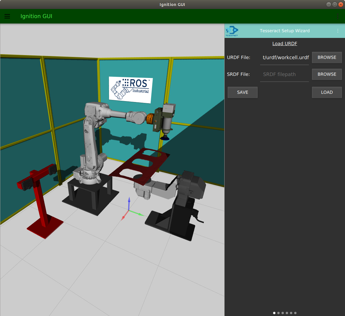
To use the wizard, first load your URDF file. Optionally load an existing SRDF to edit.
Loading files:
Drag left on the toolbar to proceed to the next page.
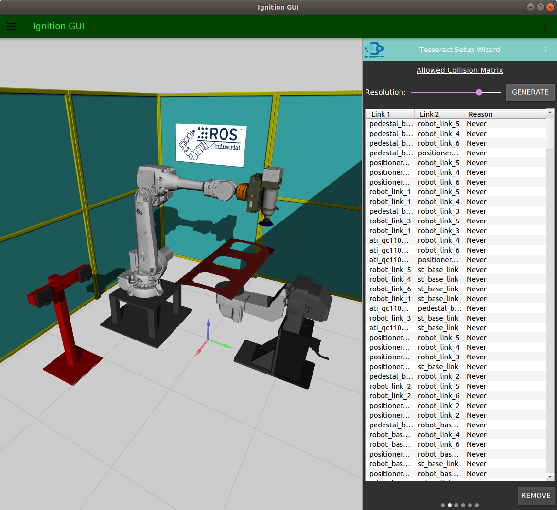
The allowed collision matrix specifies which link pairs don't need collision checking. Adjacent links and links that never collide should be disabled.
If you loaded an existing SRDF, the table will already be populated with your collision matrix.
To generate a collision matrix:
Drag left to proceed.
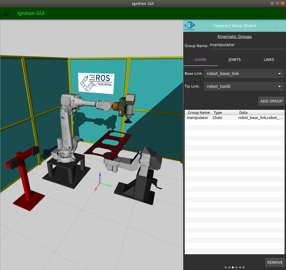
A kinematics group defines which links belong to a functional part of your robot (typically the arm used for motion planning).
Enter a group name in the Group Name field, then define it using one of three methods:
base_link)tool0 or tcp)To remove a group, select it in the table and click REMOVE.
Drag left to proceed.
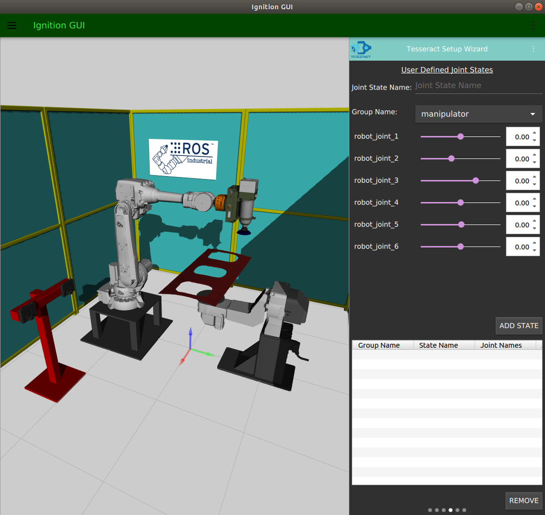
Define named robot poses (e.g., "home", "stowed", "ready") that planners can reference by name.
To define a joint state:
To remove a state, select it in the table and click REMOVE.
Drag left to proceed.
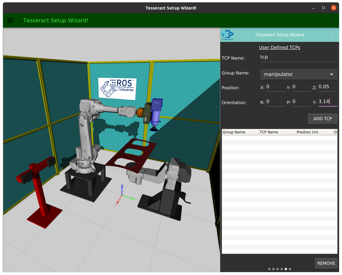
Define Tool Center Points for your kinematics groups. A TCP represents the tool's working point relative to the last link in the kinematic chain.
To define a TCP:
To remove a TCP, select it and click REMOVE.
Drag left to proceed.
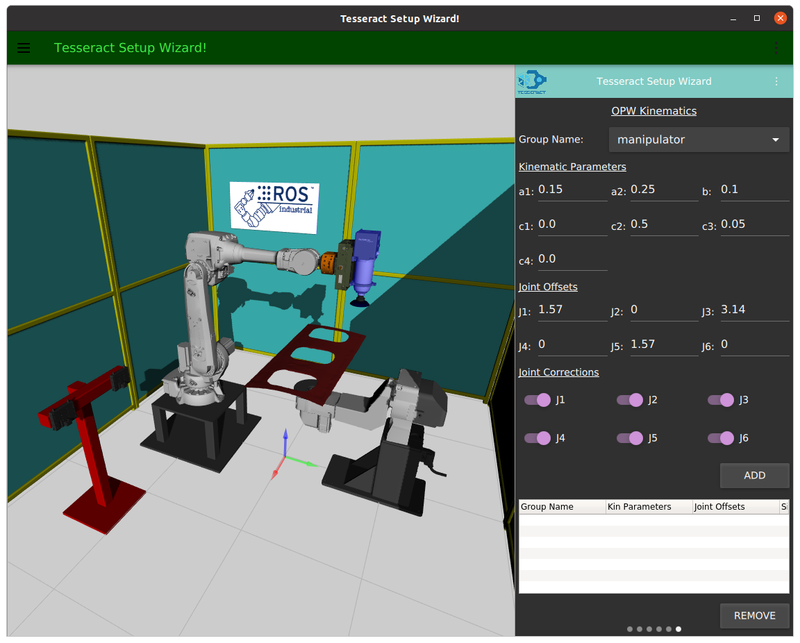
OPW is an efficient analytical inverse kinematics solver for robots with parallel bases and spherical wrists. It requires 7 measurements from your robot's specification sheet.
Use the following diagram to determine each parameter:
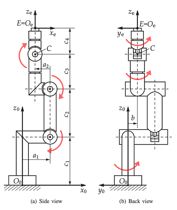
Enter each value in its respective field.
For more details on the OPW algorithm, visit the opw_kinematics repository.
Drag left to proceed.
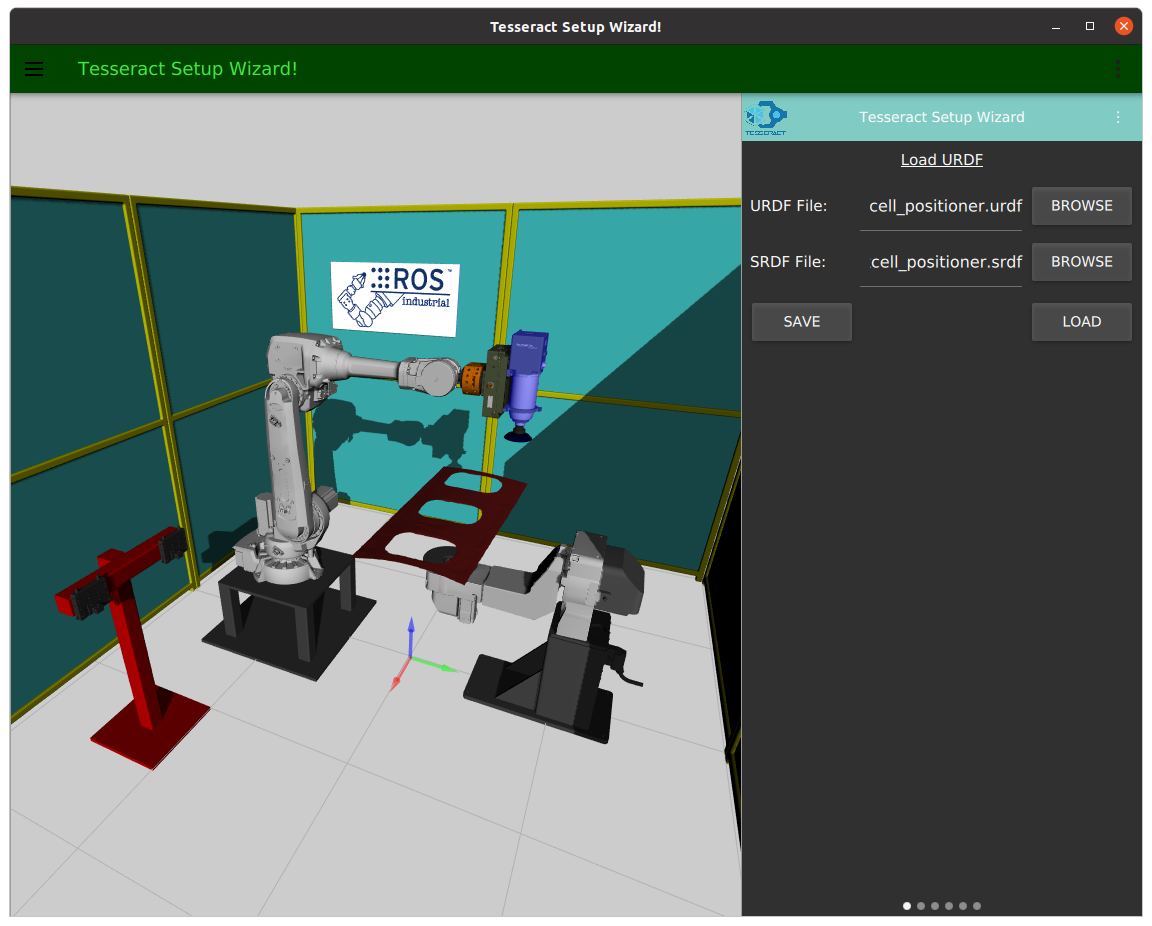
All settings — collision matrix, kinematics groups, joint states, TCPs, and OPW parameters — are stored in the SRDF file.
To save: